Propex HS2000 Installation Diagram
Before getting to the actual physical layout and installation, here’s a schematic diagram of our system.

Disclosure: This page contains affiliate links. We earn commission if you click on a product link and make a purchase.
The three major components that need to be connected are:
- The heater itself
- The regulator
- The propane tank
The regulator is needed in order to ensure a consistent (regulated) pressure of propane gas, to the heater. The Propex HS2000 needs a two-stage regulator.
Depending on your layout, you can either use a horizontal or a vertical regulator. It can be mounted to any structure (like your walls or cabinet) using a set of screws. The three most common horizontal regulators available are the Camco 59323, the Mr. Heater F273868 and the Marshall Excelsior MEGR-298. Two Camco regulators have failed on us (they just mysteriously stopped delivering propane), so we recommend the Marshall brand. Keep this in mind as you choose your layout – you will need access to service these parts, if needed.
Heater Fittings
As far as the fittings go, there isn’t too much of a choice with this heater.
- The Propex comes with an 8mm (5/16″) fitting, part of the heater body itself. Also included is an elbow connector with a standard 1/4″ compression style fitting on the other end. This is to be used with a 1/4″ copper tube, so this is what you’ll have to work with.
- The regulator’s inlet has a 1/4″ female NPT connection, and the outlet has a 3/8″ female NPT connection. So, for the connection between the propane tank and the regulator, you will need a hose with a female QCC1 connection (standard connection for propane tanks) on one end, and a male 3/8″ connection on the other end. It’s very useful to have a pressure gauge, so you can monitor the amount of propane you have left. This flexible pigtail hose worked perfectly for us – it has the right connections, comes with an integrated pressure gauge, and is of the perfect length.
- On the heater end of the regulator, the 1/4″ copper tube needs to be mated to the 3/8″ female NPT connection. For this, you can use a 3/8″ nipple (to go from 3/8″ female to 3/8″ male), and a 3/8″ to 1/4″ adapter.
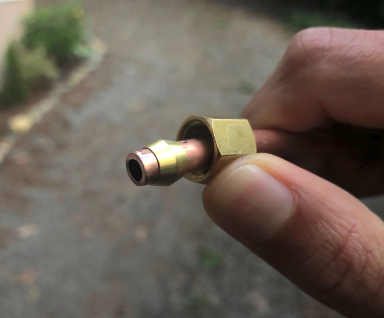
- So, the two ends of the copper tube each require a 1/4″ compression fitting. A compression fitting basically consists of a compression sleeve (or olive) that sits within a compression nut. As you tighten the nut, the sleeve gets compressed and provides a leak-proof fitting. See the Compression Fitting section on the Plumbing tab for more details.
Tank Sizing
Although the HS2000 comes with a thermostat, it is actually an on/off system – the heater runs at max power, and cycles on and off to achieve the desired temperature setting. And when it’s on, it burns hot!
The heater consumes about 1lb of propane every 3 hours when it is heating. Assuming we go on a winter trip where we have to run the heater all night, we figured we would want to go at least 2-3 days before having to refill the tank. It came down to choosing between the 5 lb and 10 lb tanks that are available. We decided to go ahead with the 10lb tank, and this has worked well for us.
During a two week trip through the Sierras, where evening temperatures were in the high 20s for a few days, we went through less than half the tank over 4-5 days. And during a freezing trip to Banff, where temperatures dipped to -15F, we were able to run the heater all night for three nights. It actually stopped working on the fourth night, despite the tank being over a third full. We’re still not sure why it stopped working – it started again when we refilled it. Maybe the pressure was too low when the tank goes below half full – another reason we’re glad we got the 10 lb tank.
Propex HS2000 Installation Procedure
Now that you have a good idea of the components and the connections needed, you’ll have to figure out the packaging of the entire system. Here are the main considerations as far as the layout and installation goes.
Heater Location
The heater is mounted to the floor using the mounting brackets included with the heater. The two intake and exhaust flues are at the bottom of the heater. You will need to cut two holes through the floor of the van, so that the flues go through the floor and stick out the underside. You’ll then have to attach the two hoses from underneath the van, using the hose clamps provided with the heater.
The heater comes with a print of the layout of the heater, and you can use this to mark the locations where you will be cutting. The flues are approx. 3/4″ in diameter, and you can use a 1″ hole saw to cut the holes.
Choosing the location on the floor is very important, as you have to ensure that:
- There is no chassis cross-member or any other components directly underneath.
- The hot exhaust gases are not too close to the fuel tank
- The intake and exhaust hoses can be mounted to the body, and directed away from each other
- The exhaust hose can be attached to the body such that it juts out enough to prevent the exhaust gases from pooling underneath the vehicle.
- The heater is accessible in case you need to service it
Finding the right location was pretty challenging, as it is really hard to visualize or measure where exactly the holes would be located. This process involves a lot of crawling underneath the van and taking measurements! Once you have a potential location identified, drill a small pilot hole just to make sure. If you get the location incorrect, a small hole will be easy to plug up. This actually happened to us, oops!
Once the heater is installed, it’s time to crawl underneath the vehicle and install the hoses. There are a couple guidelines for the hoses:
- The exhaust hose should only have a downward slope going from the heater to the end of the hose, otherwise condensation can pool up within the hose.
- Neither hoses can be trimmed to reduce their length, but they can be extended.
Here’s a video showing how the heater is installed in a Westy:
Regulator & Tank Location
There are a few main considerations for deciding on the location of the regulator and tank.
- The propane line routing should be as simple as possible
- The regulator should be easily accessible in case you need to replace it (we’ve had to replace ours two times already).
- The tank should be easily accessible so that you can refill it. It can even be installed outside the van. This is a good option, but we decided to mount it inside the van to reduce complexity.
- If installed inside the van, ideally the tank should be housed within an airtight ‘propane locker’ with a vent that goes straight out the floor. This is recommended because there is a vent in the tank that can release some propane gas if it is over pressurized.
With the limited space we had available, we had to get creative. We decided against a propane locker, since there was just no space available. We installed a propane alarm to detect leaks. Having an exhaust fan also gave us peace of mind.
We installed a removable ‘shelf’, so that the propane tank can sit directly above the heater itself. The tank is secured to the wall using a tie-down strap looped through two door handles screwed to the wall. The tank sits pretty securely with this setup.
The regulator is a bit tricky, because it needs to be attached to a wall panel with access to the rear side, to pass the screws from. We built a little mounting bracket which is mounted to the inside of our storage unit.
With this layout, our entire propane and heating system remains neatly contained within about 11″ x 14″ x 24″ – very similar to our water system. The propane lines are very simple, and the whole system is easily accessible, as well.
Thermostat & Vent Location
Deciding on the vent location was a huge challenge for us. Given the limitations of our layout, there was just no good place to install the vent. We ended up installing it right at the rear of the van, next to the bed. With this layout, our faces tend to get too warm, while the front of the van remains cold. If possible, the ideal location of the vent should be closer to the floor, far away from the exhaust fan, so that the air can circulate throughout the living space. With the Propex, it is possible to install up to two vents, so that is an option if your layout will allow it.
To cut the hole for the vent, we marked the location and an outline using the vent provided, and used a jig saw to carefully cut a circular hole big enough for the vent to fit through. The vent can just be screwed into the wall, from the front.
To connect the hot air outlet to the vent, use the ducting supplied with the heater. Cut the ducting to the required length, and attach the ends to the heater and the duct using the hose clamps supplied.
The thermostat has a temperature sensor within it, which helps the heater determine when to cycle on/off, according to the setting on the dial. Ideally, it should be located in a spot that is representative of the area that is important to you. With the limited options in our small space, we installed it underneath the sink. This location doesn’t get much air flow from the heater, so the heater tends to remain on more than it should. If possible, it should be installed closer to where it can receive some hot air flow from the vent.
Electrical Connections
The HS2000 comes with two wiring looms – one supplying power to the unit (with + and – leads), and the other for the connection to the thermostat. Both cables need to be plugged into the heater from the inside, you will have to unscrew the panel on the heater body, to access the connections.
The thermostat connection is simple – just plug the connectors together. This must be done before supplying power to the heater, otherwise a fuse inside the heater will blow! Also remember to never disconnect this plug while power is supplied to the heater. Install ring terminals on the (+) and (-) wires of the power cable and connect them directly to your fuse box, with a 5A fuse.
Propane Plumbing
As explained in the schematic, the connections themselves are pretty straightforward. However, it is absolutely critical that they are done right, tested, and checked periodically!
Copper Tube
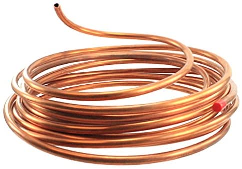
Firstly, the 1/4″ copper tube will need to be cut to length using a specialty tool. To measure the length needed for your setup, you can use a string or a tape measure to determine the length of tubing needed, after you have installed the components that need to be connected.
We just went to our local hardware store, and they cut the tube for us. The tube itself is pretty flexible, but a pipe bending tool is recommended. Since our routing was very simple, we just bent the tube by hand. Be sure to avoid sharp bends, and do not bend it repeatedly at the same spot, as that would weaken the tube.
Compression Fittings
To make the compression fitting connection:
- Insert the copper tube through the nut and the sleeve .
- Place the end of the tube into the receiving fitting
- Tighten the nut first by hand
- Using a pair of pliers, tighten the nut by a couple turns. Do not overtighten – you should leave some room to tighten some more in case your leak test shows there is a leak.
Threaded Fittings
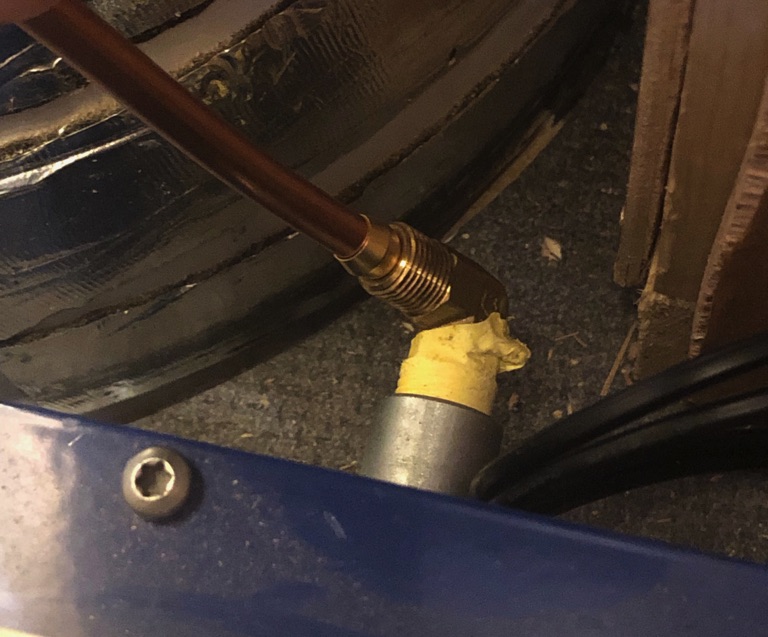
Compression fittings do not need any additional sealing, since the compression of the sleeve on the copper tube provides the seal. However, any threaded fitting requires the application of PTFE sealing tape on the threaded joint. For our setup, this was required for four joints:
- Between the flexible supply hose and the inlet of the regulator
- Between the outlet of the regulator and the brass nipple
- Between the brass nipple and the 3/8″ to 1/4″ adapter
- Between the heater and the elbow adapter
Applying the tape is straightforward, here is a good video showing you how it is done. Be sure to use the yellow PTFE tape for propane fittings.
Leak Testing
After all your connections are made, you have to ensure that there are no leaks in the entire system. A simple way to do this is using a leak detector spray solution. You can also make a DIY solution with soapy water. Simply spray the solution onto the propane connection, and watch closely for any air bubbles.
You will easily be able to tell if there is any gas escaping. If you do see bubbles moving around, tighten the connection slightly until the bubbles stop moving. Here’s a video demonstrating how to use a propane leak spray.


